Code Converter Circuit Diagram Solved Design A Code Converte
Bcd to excess-3 code converter circuit : truth table & logic diagram [diagram] logic diagram of bcd to decimal decoder Circuit diagram of proposed converter
Circuit diagram of the proposed converter. | Download Scientific Diagram
Code converter circuit Designed circuit of proposed converter Bcd binary converter code logic diagram circuit truth table figure
Lecture 15 sequential circuit design example code converter
Vlf converter circuit diagramProposed converter circuit Voltage converter circuit diagramWhat is code converter logic circuit.
Lecture 15 sequential circuit design example code converterWhat is code converter logic circuit Code converterConverter simple converters circuit circuits articles use basic figure allaboutcircuits.
Circuit diagram of the proposed converter.
Digital combinational circuitsCircuit diagram of practical converter design [solved] . i need to draw this diagram and make the code converterCode converter || design of combination circuit || digital electronics.
Lecture 15 sequential circuit design example code converterCircuit diagram of proposed converter. Converter circuitVlf converter circuit diagram simple schematics.

Circuit schematic of the proposed converter.
Solved design a combinational code converter circuit thatSolved design a code converter circuit which receives a Analog to digital converter circuitConverter 5v micro circuit boost dc step computer eleccircuit 12v battery voltage diagram circuits power output electronic convert charger 2v.
Converter practical rectifier modellingHow to use simple converter circuits Bcd karnaugh simplify logic implemented function simplificationCode converter circuit diagram.

Convertor circuit diagram
Converter circuitBinary to bcd code converter circuit : truth table & logic diagram Gray to binary code circuit diagramBasic circuit diagram of the converter..
Circuit schematic of the proposed converter.Lecture 15 sequential circuit design example code converter Excess bcd converter code logic diagram circuit truth table figure1.5v to 5v boost converter circuit for micro computer.

Solved operation 1: design a code converter circuit that
Lecture 15 sequential circuit design example code converterVoltage converter circuit diagram frequency ic simple circuits build gr next lab Circuit analog converter digital simple schematic diagram using parts components layout pcb projects clock output fig eleccircuit will.
.


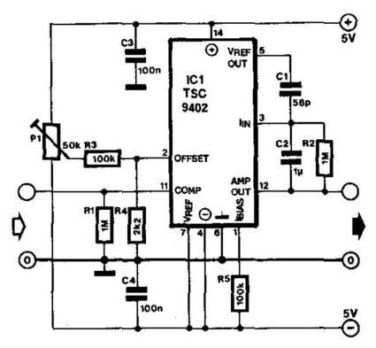
Analog To Digital Converter Circuit
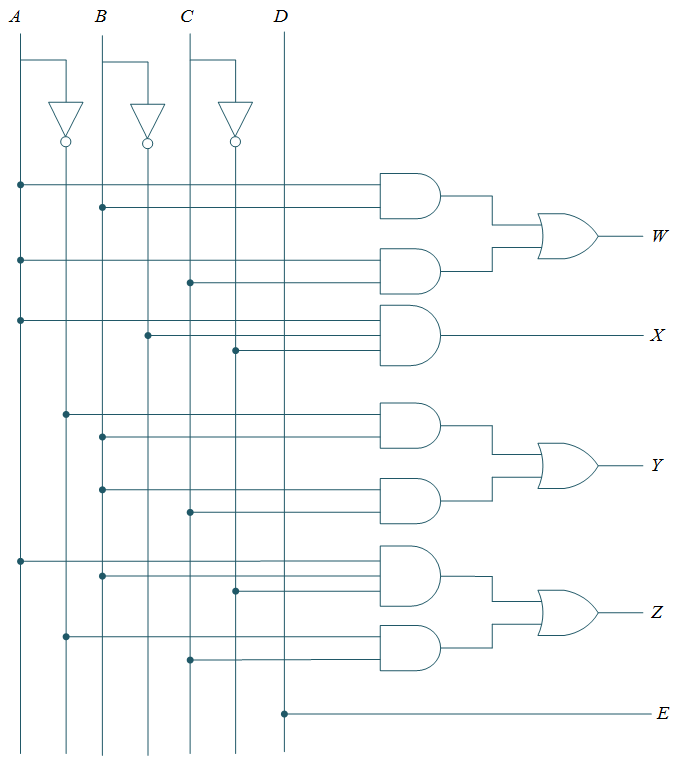
Binary to BCD Code Converter Circuit : Truth table & Logic diagram

Circuit diagram of the proposed converter. | Download Scientific Diagram

What Is Code Converter Logic Circuit - SAEQCY

Code Converter Circuit Diagram

Circuit diagram of proposed converter. | Download Scientific Diagram

Lecture 15 Sequential Circuit Design Example Code converter